You now this click clack noises for exmple from your car if you want to turn right or left, yes right I mean relay. This will be the stuff that describe in this post, controlling circuits with a relay.
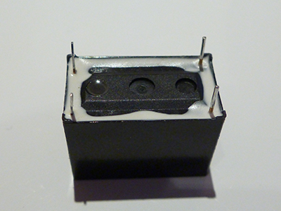
I used the following relay in my examples:
Power Relay V05SKT – Datasheet
Maximum Switching Current 5 Ampere
Maximum Switching Voltage 250 VAC, 150 VDC
Minimum Switching Load 3 Volt or 5 V at 100mA
High insulation with reinforced insulation system (between coil and contacts)
Coil connection: 1 and 4
Current connection: 2 and 3
You can find the coil by the mark on the side of your relay case or by line on the top of your relay. Another way: you try to measure the electrical resistance with a multimeter – Ω position, only the coil can be measured by the digital multimeter.
Arduino INO Code:
int RelayPIN = 12; void setup() { pinMode(RelayPIN, OUTPUT); } void loop() { digitalWrite(RelayPIN, HIGH); delay(1000); digitalWrite(RelayPIN, LOW); delay(1000); } |

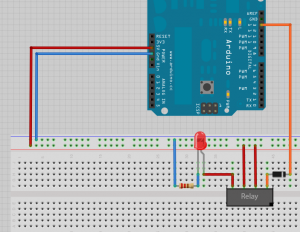
Pin 12 will be used for switching load, and will be connected to the coil, it doesn’t matter where is plus and minus.
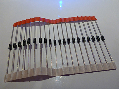
To protect the arduino arduino board I used a diode:


Leave a Reply